|
Construction of an electronically
controlled automated water pumping controlling system
Undergraduate
Reserch Project 2005/2006: FSC32P2
Faculty of Science
University of Ruhuna
Matara 81000, Sri Lanka.
No part of this document may be copied/stored in any of the
printed or electronic
versions/devices without permission from the author of this
document and the inventor
of the device which is described in this document.
|

|
Author/Inventor
R.K Damith Kumara
Tele 0773664729
Siriyagama
Bundala
Weligaththa
Hambantota
|
The
system constructed here consists of following main circuit components
and parts.
-
The
sensors, which sense the water levels in the well and the tank.
-
The
voltage regulator that monitors the variation of the voltage.
-
The
main circuit to control the system.
-
The
digital display.
-
The
buzzer.
-
The
optional switch.
The
circuit is designed to operate as follows.
When the water level of the tank is lower than the sensor that is
closer to the bottom of the tank. The motor is turned ON through the
relay. This continues even after the lower sensor goes under water.
When both sensors are in contact with water, Then the motor is turned
OFF through the relay stopping the pumping.
When water is used, the water level eventually drops below the upper
sensor. However, won’t turn on the power to the motor again. In
order to turn on the motor both sensors should not contact with
water. Therefore the pumping will start only after the water level
drops below the lower sensor. This logic is illustrated in the Table
1.
|
Upper Sensor
|
Lower Sensor
|
Motor
|
|
1
|
1
|
ON
|
|
1
|
0
|
ON
|
|
0
|
0
|
OFF
|
|
1
|
0
|
OFF
|
|
1
|
1
|
ON
|
Table 1:
Conditions to turn on and off the motor depending on the signals from
the sensors in the tank.
As
can be seen above (Table 1), the motor turns on when both sensors
upper from water and turn off when both sensors contact with water.
After the motor is turned on, it keeps on the upper sensor contact
with water, respectively and for the same combination motor is
maintained at off state after the motor is turned off. In order to
perform this function the previous conditions should be stored.
During
the pumping of water the water level in the well drops. In the event
the water level is dropping below the upper censer, the motor would
not turn off even though the upper censer does not contact with
water. However, the motor will turn off automatically if both sensors
does not contact with water, which could happen only when the water
level is below the lower censer in the well. This condition
guarantees that the pumping continues only if the water level is
above the put valve. If this happens during the pumping the motor
will start again when both sensors contact with water. i.e., after
the water level is above the upper sensor in the well. This logic is
illustrated in the Table 2.
|
Upper Sensor
|
Lower Sensor
|
Motor
|
|
0
|
0
|
ON
|
|
1
|
0
|
ON
|
|
1
|
1
|
OFF
|
|
1
|
0
|
OFF
|
|
0
|
0
|
ON
|
Table 2:
Conditions to turn on and off the motor depending on the signals from
the sensors in the well.
The buzzer is to indicate the low water level of the well. if the
water level is below the lower sensor which is just above the put
valve, then motor is turned off and the buzzer is turned on and the
indicating that the motor turned off due to low water level in the
well.
The motor is OFF when the tank is filled up to the higher level and
it starts again when it goes pass the lower level of sensor. A
digital display is constructed to indicate the water level of the
tank. four different water sensors are used to determine the water
level of the tank. depending on the water level in the tank the
display will indicate one of the five regions in the tank depending
on the height. This will be displayed by a digit in the display from
0 to 4 with 4 indicating the highest level.
The voltage regulator unit monitors the fluctuations of the supply
voltage. When the supply voltage reaches a set value above which the
motor and the component of the circuit could damage, the unit
automatically cut off the main supply to the main circuit and the
motor. This will protect the motor and the other component of the
system from damages due to high voltages. when the supply voltage is
in the range between 200V to 250V AC the regulator provides a
constant 12V DC to all circuits. The relay is turned on only if the
supplied voltage is within the above range for the protection of
instruments. The range can be adjusted manually if needed. If the
supply voltage were out of the selected range the power would not
supply to the circuit. When the power is back to the safe range again
the circuit will turn on with a delay of 21/2
minutes. Similarly, the regulator will deliver power to the
circuit with the same delay after a power failure, if any, in the
house hold power supply. Hence the motor will be safe for unexpected
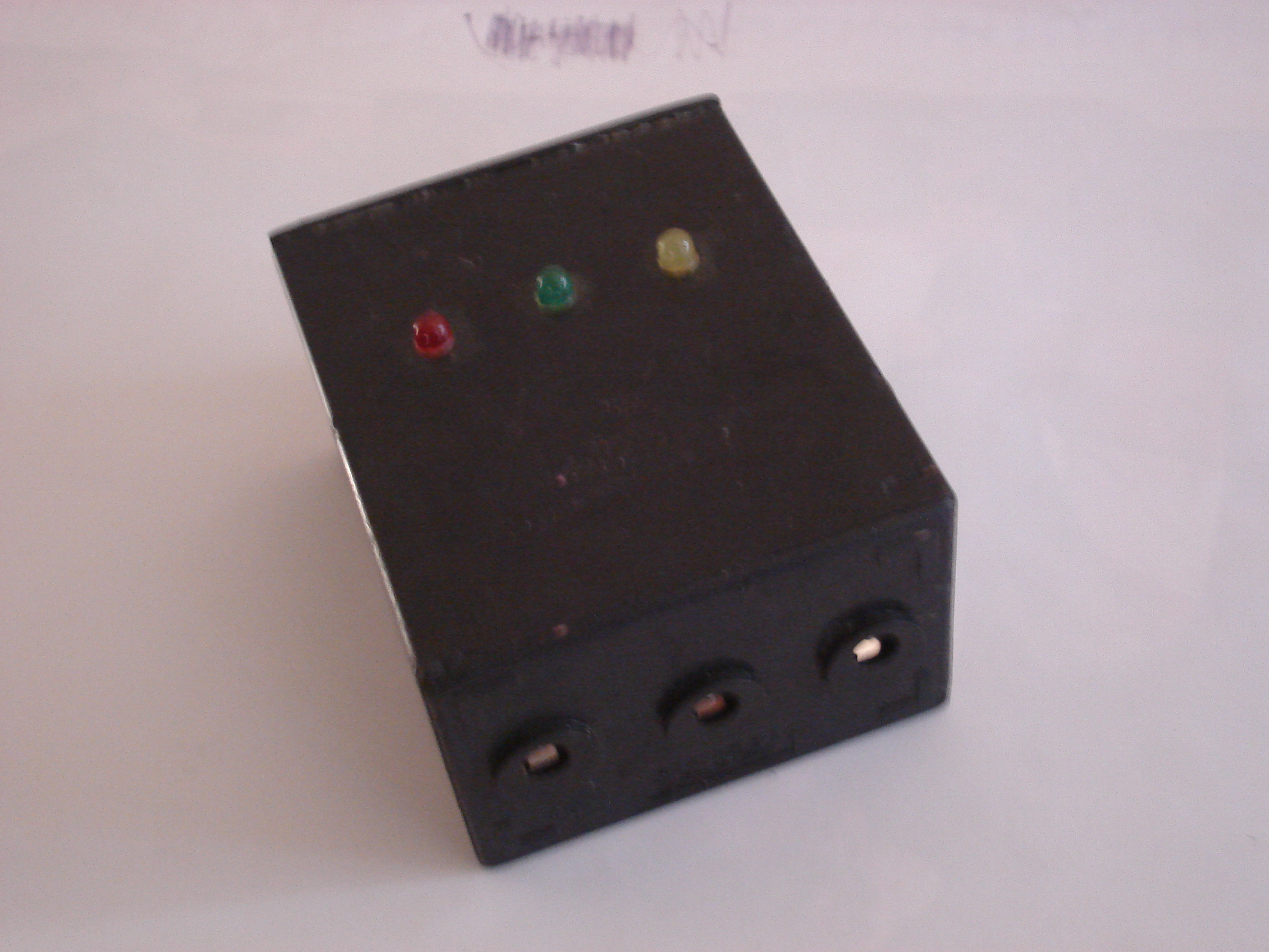
power fluctuations. The level of the voltage, whether the voltage is
higher, lower or at the relevant voltage level, is displayed using
state indicator LED. The red LED in higher voltages, yellow in lower
voltages and green one in relevant value and blinking green during
the delay time. That would indicate the quality of the power supply
and whether the relay is ON or OFF.
In case if one wants to fill the tank before the water level drops
below the lower sensor in the tank then one could use the push button
switch. This will turn on the motor regardless of the water level in
the tank. The motor will stop when the tank is full up to the upper
sensor. For example, if the water level is just above the lower
sensor and one wants to make sure that the tank has sufficient water
to take a bath in order to avoid the situation of not having water
during the bath due to a power failure, then the push button switch
can be used to fill the tank.
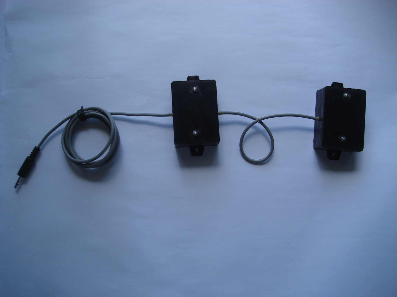
Water Sensor for well
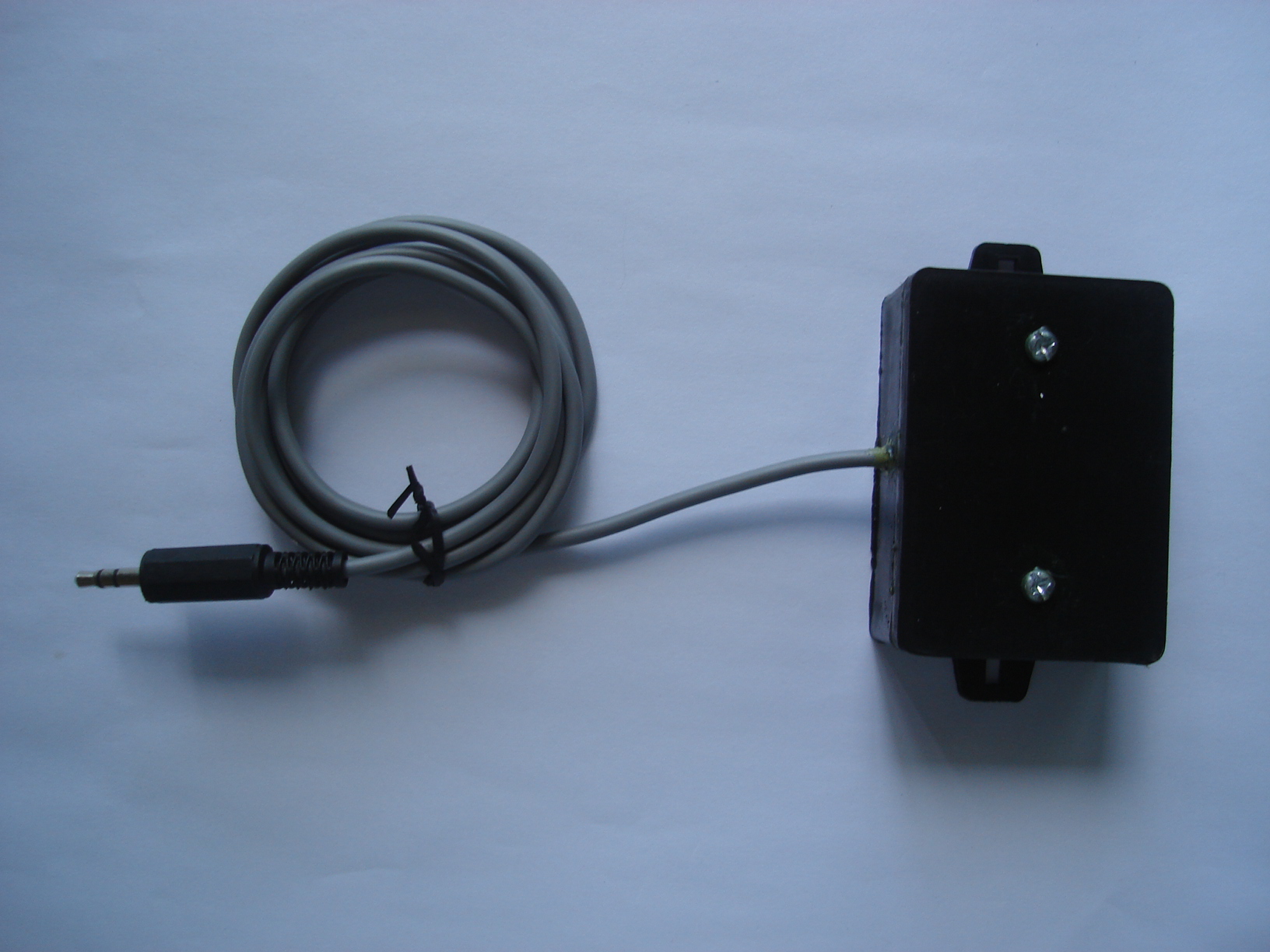
Water Sensor for Tank
Voltage Regulator Unit
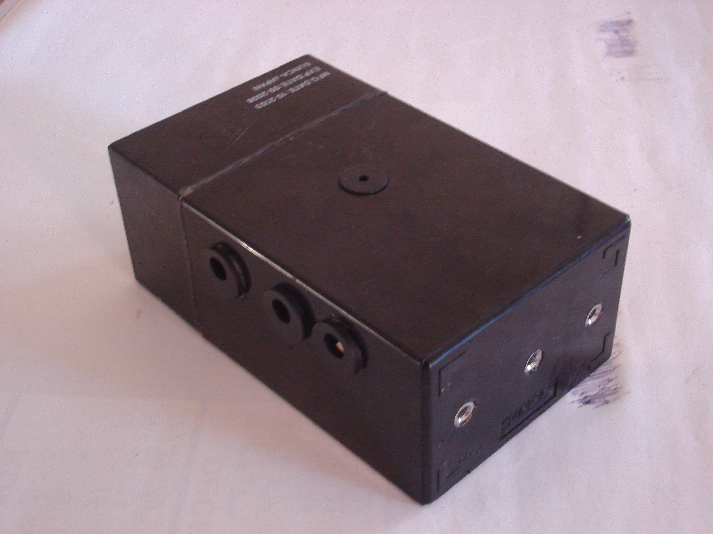
Main
Circuit
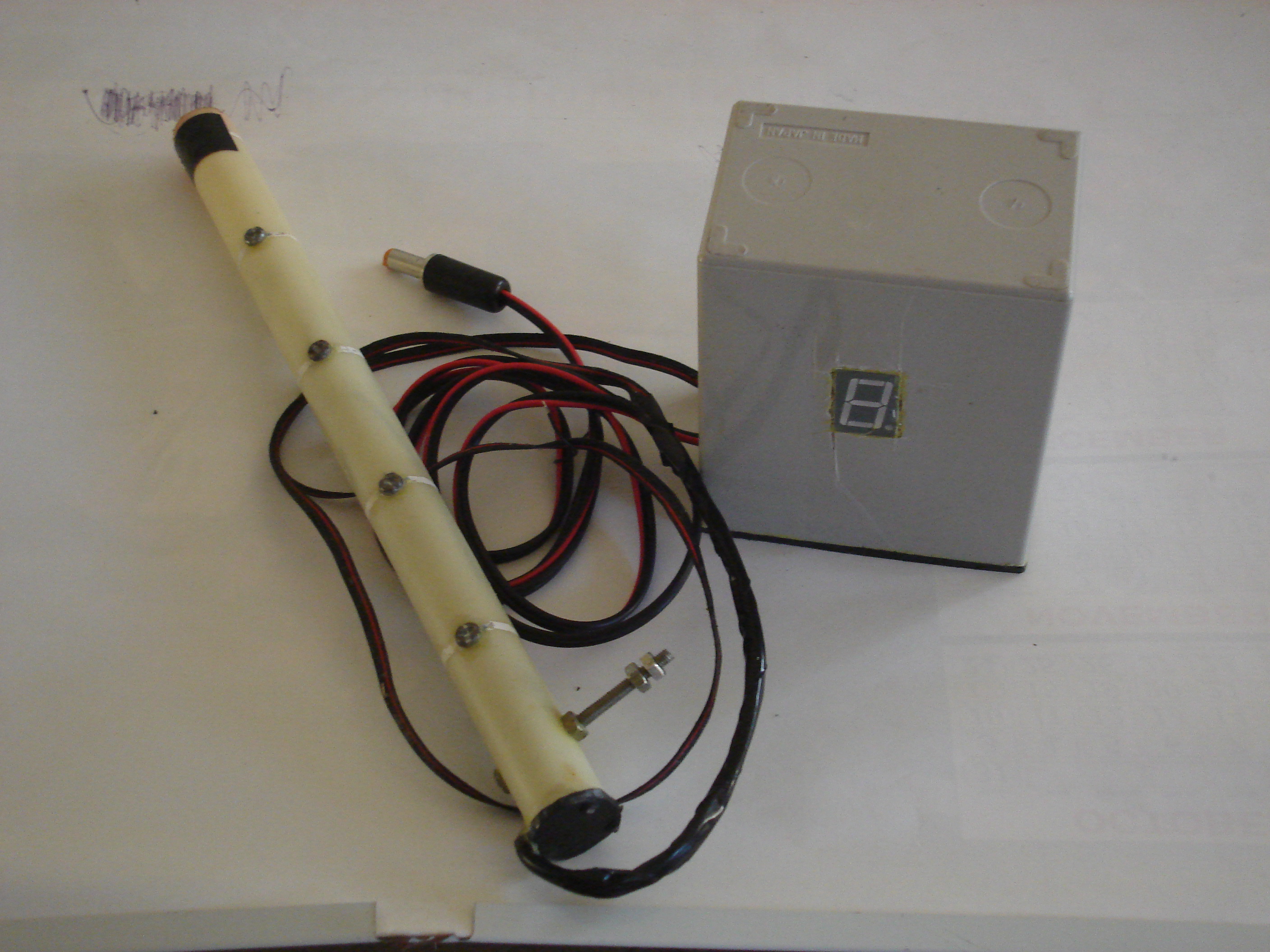
Digital
Display
Copyright by, R.K Damith Kumara, Siriyagama,
Bundala, Weligaththa, Hambantota